What is UHF RFID multi-antenna identification system?
What is UHF RFID multi-antenna identification system?
1、 Overview
Radio Frequency Identification (RFID) is a low-power short-range wireless communication technology. The full name is "Radio Frequency Identification (RFID)". The RFID identification system consists of at least two components: a radio frequency tag (Tag) and a reader/riter (Reader/riter or Interrogator). Radio frequency tags store electronic data in a specified format. In actual applications, electronic tags are attached to the surface of the object to be identified. The reader/riter can read the electronic data stored in the radio frequency tag without contact, thereby achieving the purpose of identifying the object information. The computer and network are combined to realize the collection, processing and remote transmission of object information and other control functions. The RFID identification system with an ultra-high frequency working frequency is applied in many fields such as production line automation management and warehouse management due to its strong tag recognition ability and fast data transmission rate.
In the warehouse management application of large supermarkets, due to the diversity of packaging materials and the uncertainty of the number of items, some tags attached to the packaging of items will not be recognized, that is, there is a problem of blind recognition within the signal coverage range. The occurrence of this phenomenon seriously affects the promotion of RFID identification systems in warehouse management applications. In order to improve the tag reading rate and recognition reliability of RFID identification systems, domestic and foreign researchers have conducted a lot of research work, including a lot of application research on multi-reader antenna identification systems. By rationally deploying multiple antennas connected to readers at different spatial locations, the coverage area of each antenna is complementary, reducing the reading and writing blind spots of the RFID identification system. This paper improves the multi-antenna solution proposed by Chen Hui et al. of Chongqing University from two aspects: spatial deployment of multiple antennas and optimization control algorithm of multiple antennas, further improving the tag reading rate and recognition reliability of RFID identification systems.
2、Improvement plan for RFID multi-antenna identification system
2.1 Analysis of antenna deployment position
The multi-antenna layout proposed by researchers such as Chen Hui is shown in Figure 1.
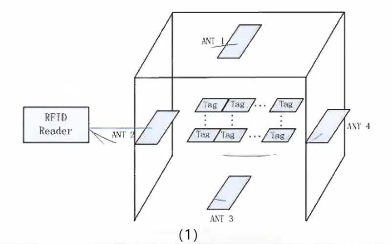
The four antennas connected to the reader are deployed in the upper, lower, left and right directions of the identification area, and the order of antenna activation is ANT1, ANT2, ANT3, and ANT4. The coverage ranges of the four antennas connected to the reader are complementary, reducing the identification blind area of the reading and writing area. However, in actual applications, the RFID identification system is deployed in the channel, and the reader antenna below is difficult to deploy. If the antenna below the identification area is removed, the system's coverage of the identification blind area will be reduced. This paper takes into account that in the actual application of the RFID identification system, the orientation of the tags in the identification area is uncertain. The layout of deploying the reader antenna in the upper left, lower left, upper right and lower right directions is equivalent to the layout of the reader antenna distributed in the upper, lower, left and right directions, and solves the problem of difficult deployment of reader antennas in actual applications. The improved multi-antenna layout is shown in Figure 2.
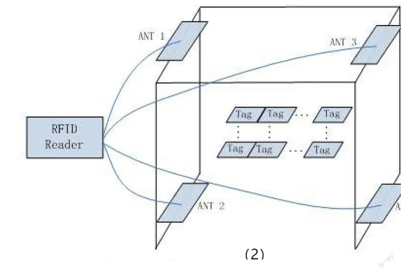
The relative position of the reader antenna and the tag antenna plays an important role in the distribution of blind spots in the system identification area. In the multi-antenna layout scheme in the figure above, the identification blind spots in the coverage area of the ANTI antenna are not necessarily the blind spots of the other three reader antennas. Therefore, it can be said that multiple reader antennas are deployed at different locations around the system identification area to complement each other. This reader antenna spatial diversity scheme can effectively remove blind spots in the identification area.
There are many ways to reduce the blind spots of RFID identification systems. Compared with other methods such as frequency diversity, the method of using spatial diversity can achieve a better effect of removing blind spots, because in the ultra-high frequency RFID working frequency band, the wavelengths of electromagnetic waves corresponding to different frequencies are not much different, and the final blind spot distribution is basically the same, and the effect of eliminating blind spots will not be very obvious.
2.2 Analysis of multi-antenna control algorithm
In practical applications, RFID identification systems are generally required to be able to identify all tags in the identification area without omission and to complete the entire identification process as quickly as possible. In a multi-antenna identification system, the time used for the identification process of each antenna is a basic antenna inventory cycle. When the system performance is tested with the maximum number of tags allowed by the identification system, the identification system can meet the requirement of no tag missed reading. However, in many practical applications, the number of tags that need to be identified is far less than the maximum number of tags allowed by the system. At this time, a situation will arise. When the basic inventory process of the first antenna is completed, all tags in the identification area have been identified. Then the time spent on the inventory process of the remaining three antennas is unnecessary, resulting in a waste of system resources. This paper improves the control method of multiple antennas in view of this situation, so as to improve the efficiency of the identification system.
The key point of the multi-antenna control algorithm is to determine the order of antenna opening. Since the orientation of the tags in the system identification area is uncertain in practical applications, the first antenna to be started can be random. This paper sets ANTI as the first antenna to be turned on. Determining the second antenna to be turned on is a difficult point. This paper determines the second antenna to be turned on by analyzing the relative position of the reader antenna and the tag antenna. Li Peng and others from the University of Electronic Science and Technology of China conducted an experiment on the influence of the relative position of a single reader antenna and a tag antenna on the recognition rate. The experimental results show that in the process of relative position from parallel to vertical, the tag recognition rate gradually decreases. The recognition rate is the highest when the tag plane is parallel to the reader antenna plane, and the recognition rate is the lowest when the tag plane is perpendicular to the reader antenna plane. Based on this, it can be determined that ANT2 or ANT3 antenna is the most suitable as the second antenna to be turned on, because the tag perpendicular to the ANT1 antenna plane is parallel to the ANT2 and ANT3 antennas, ensuring that the tag perpendicular to the ANT1 antenna can obtain a higher reading rate during the inventory process of the second antenna. This paper sets the ANT2 antenna as the second antenna to be turned on. The order of turning on the third and fourth antennas refers to the process of determining the order of turning on the second antenna. Finally, the order of turning on the four antennas determined in this paper is ANT1, ANT2, ANT3, and ANT4. At the end of the basic inventory cycle of each reader/writer antenna, the set of tags recognized by the system after the inventory process of this reader/writer antenna is completed is compared with the set of tags recognized by the system before the inventory of this antenna. If new tags are recognized, it means that there may be tags that are missed by the recognition system. In order to reduce the possibility of unrecognized tags in the system, it is necessary to continue to open the next reader/writer antenna to read the tags; if no new tags are recognized after the inventory cycle of the reader/writer antenna is completed, this situation where no new tags are added is regarded as the end point of the entire recognition process of the system. Compare the sets of identified tags before and after the end of the system inventory. The larger the number of tags contained in their intersection, the lower the possibility of missed reading by the recognition system. The flowchart of the multi-antenna control algorithm is shown in Figure 3. The variable marked with A in the flowchart represents the set of tags recognized by a single reader/writer antenna.

The multi-antenna control algorithm determines the antenna opening order based on the ideal model of random tag orientation. In actual applications, the orientation of tags may be concentrated in one or several directions. Therefore, statistically analyzing the orientation of tags and determining the antenna opening order based on this is also an important aspect to improve the efficiency of the recognition system. This paper recommends that each antenna be assigned a weight in actual applications. The initial weight is 0. After the recognition system completes the inventory of tags, the number of tags identified by the opened antennas is compared, and the weight of the reader antenna with the largest number of identified tags is added by 1. When the reader antenna opening order is initialized during the next inventory process of the recognition system, the opening order is determined by the weight of the reader antenna. If the weights are the same, it is determined according to the ideal model.
3、Performance Analysis of UHF RFID Multi-antenna Identification System
3.1 Parameters for Reliability Evaluation of RFID Identification System
The multi-antenna layout of RFID identification system can reduce the phenomenon of missed reading of tags when identifying multiple tags, improve the reliability of RFID identification system for multiple tags, and select the parameters that can indicate the reliability of the identification system from the parameters that appear in the inventory process of the multi-antenna identification system. This paper defines this parameter as the system reliability coefficient.
Definition 1: The system reliability coefficient μ is the ratio of the number of tags N identified by all the opened antennas during the system inventory process to the total number of tags N identified by the system.
In formula (1), ue10,11, this parameter reflects the situation that the identification system is affected by unreliable factors during the inventory process of tags. The smaller the parameter value, the greater the impact of unreliable factors on the identification system, and the lower the reliability of the system. Conversely, the higher the reliability of the identification system. When the value of U is 1, the reliability of the identification system is the highest. At this time, it can be considered that there is no missed reading during the entire inventory process.
3.2 RFID identification system simulation analysis
System simulation parameter settings: The number of tags to be identified is N=300, and the number of multiple antennas has been determined to be M=4. After the simulation parameters are determined, this paper conducts 100 system identification simulations and analyzes the simulation results.
Setting of system simulation parameters: The number of tags to be identified is N=300, and the number of multiple antennas has been determined to be M=4. After the simulation parameters are determined, this paper conducts 100 system identification simulations and analyzes the simulation results.
First, the relationship between the single antenna reading rate p and the number of tags identified by the system and the number of antennas activated is analyzed. The simulation results are shown in Figure 4. The probability p is the recognition rate of a single antenna to a tag, that is, the probability that each tag to be identified can be identified. The larger the value of p, the larger the intersection of the tag sets identified by all enabled antennas, and the less the identification system is affected by unreliable factors.

Figure 4(a) is a curve showing the total number of tags identified by the system as a function of the single antenna reading rate p. This curve shows that the number of tags identified increases with the increase of the p value. After the p value is greater than 0.6, the total number of tags actually identified by the system is close to the number of tags to be identified, 300. Figure 4(b) is a graph showing the number of antennas actually turned on by the system as a function of the single antenna reading rate p. This graph shows that the number of antennas actually turned on by the system decreases as the p value increases. Two key points can be seen in Figure 4(b). When the p value is less than 0.5, the number of antennas actually turned on by the system is 4. When the p value is greater than 0.9, the number of antennas actually turned on by the system is mostly two. According to the characteristics of the multi-antenna control algorithm, the number of antennas turned on by the system is at least two. Therefore, when the p value is 1, the number of antennas turned on is also two. Figure 4(c) is a curve showing the change of the system reliability coefficient as a function of the single antenna reading rate p. This curve shows that the value of the system reliability coefficient u increases as the P value increases. That is, the larger the P value, the higher the system reliability. When the p value is less than about 0.4, the system reliability coefficient is close to 0.
The relationship between the number of antennas turned on by the identification system and the system reliability coefficient is shown in Figure 5.

Figure 5 is a graph showing the number of antennas actually turned on by the identification system as a function of the system reliability coefficient u. It can be seen from the figure that when the system reliability coefficient is less than 0.6, because the total number of antennas is 4, the number of antennas actually turned on by the system is the maximum number of 4. When the u value is greater than 0.8, the number of antennas turned on by the recognition system begins to show a trend of decreasing.
From the above analysis of the recognition system simulation results, it can be seen that the RFID multi-antenna recognition system can improve the reliability of multi-tag recognition, and the introduction of multi-antenna control algorithm improves the efficiency of the recognition system. The system reliability coefficient u provides an indicator that can evaluate the reliability performance of the recognition system.
4、Conclusion
The UHF RFID multi-antenna identification system adopts the method of spatial diversity to reduce the reading and writing blind area of the RFID identification system, thereby improving the reliability of the RFID identification system. The introduction of the multi-antenna control algorithm has also improved the system efficiency, achieved the purpose of quickly and reliably identifying a large number of tags, and provided a parameter that can be used to evaluate the reliability of the identification system, namely the system reliability coefficient. The simulation results show that the UHF RFID multi-antenna identification system has a significant effect on improving the reliability of multi-tag identification, which is an important aspect of the research and wide application of multi-tag leak-free identification technology.

Pro RFID & BarCode
www.yanzeorfid.com

Pro RFID & BarCode
Navigation
News


